

Product Details
Place of Origin: dongguan,China
Brand Name: HOTHMI
Model Number: HTG9696A
Payment & Shipping Terms
Minimum Order Quantity: 2
Delivery Time: 25 days
Payment Terms: L/C, D/A, T/T, D/P, Western Union, MoneyGram
Supply Ability: 99999
Product Type: |
COG |
Display Content: |
96X96 |
Product Application: |
Handheld Devices |
Viewing Angle: |
6H |
Number Of PINS: |
28PIN |
Driver Chip Model: |
SSD1848 |
Backlight Type Or Brightness: |
White Light |
Interface Mode: |
MCU/8bit |
Product Type: |
COG |
Display Content: |
96X96 |
Product Application: |
Handheld Devices |
Viewing Angle: |
6H |
Number Of PINS: |
28PIN |
Driver Chip Model: |
SSD1848 |
Backlight Type Or Brightness: |
White Light |
Interface Mode: |
MCU/8bit |
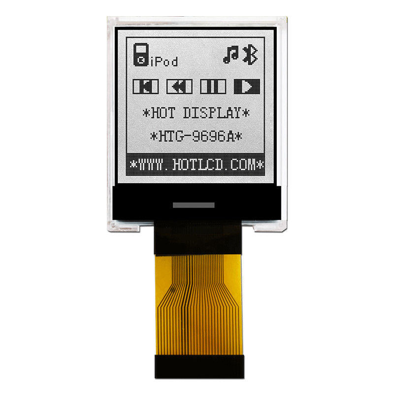
96X96 Graphic COG LCD SSD1848 | FSTN + Display With WHITE Backlight/HTG9696A
Product parameters
| ITEM | STANDARD VALUE | UNIT |
| Number of dots | 96X64 DOTS | ---- |
| Module dimension | 35.9x29.9x2.9 | mm |
| View display area | 25.0x25.0 | mm |
| Dot size | 0.205x0.205 | mm |
| Dot pitch | 0.23x0.23 | mm |
| Operating temp | -20~70 | ℃ |
| Storage temp | -30~80 | ℃ |
|
Driving Method |
1/ 128 DUTY,1/ 12 BIAS,VOP= 3.3V |
|
|
Viewing direction |
6 O’CLOCK |
|
|
Display mode |
FSTN |
|
|
Display type |
TRANSMISSIVE / NEGATIVE |
|
|
Driver IC |
SSD1848 |
|
| Backlight | WHITE | |
Mechanical Data
| Item | Standard Value | Unit |
|---|---|---|
| Module Dimension | 35.9x29.9x2.9 | mm |
| Viewing Area | 25.0x25.0 | mm |
| Mounting Hole | 22.055x22.055 | mm |
| Dot Pitch | 0.205x0.205 | mm |
| Dot Size | 0.24x0.22 | mm |
Electrical Characteristics
| Item | Symbol | Standard Value typ. |
Unit |
|---|---|---|---|
| Input Voltage | VDD | 3.3v | V |
| Pin No. | Pin Name | Function | |||||||||||||||
| 1 | VSS | This is a logic ground pin. It must connect to GND from external supply | |||||||||||||||
|
2 |
PS0 |
PS0 and PS1 determine the interface protocol between the driver and MCU. Refer to the following table for details.
Note: The above H refers to either VDDIO while L refers VSS |
|||||||||||||||
| 3 | VDD | This pin is the system power supply pin of the logic block. | |||||||||||||||
| 4 | PS1 | Like SP0 | |||||||||||||||
| 5 | /CS | This pin is chip select input. | |||||||||||||||
| 6 | /RES |
This pin is reset signal input. When the pin is low, initialization of the chip is executed. |
|||||||||||||||
| 7 | D/C | This input pin is to identify display data/command cycle. | |||||||||||||||
| 8 | R/W | When R/W = “H”: Read. When R/W = “L”: Write. | |||||||||||||||
|
9 |
E |
This pin is MCU interface input. When 6800 interface mode is selected, this pin will be used as the Enable (E) signal. Read/ write operation is initiated when thispin is pulled high and the chip is selected. When 8080 interface mode is selected, this pin is the Read (RD) control signal input. Data read operation is initiated when this pin is pulled low and the chip is selected. |
|||||||||||||||
| 10~17 | DB0~DB7 | 8-bit data bus lines | |||||||||||||||
| 18 | VDD | This pin is the system power supply pin of the logic block. | |||||||||||||||
| 19 | VSS | This is a logic ground pin. It must connect to GND from external supply | |||||||||||||||
| 20 | VOUT | This pin is the most positive LCD driving voltage. | |||||||||||||||
| 21 | C4+ |
Connect an external capacitor to these pins when 4X, 5X, 6X or 7X DC-DC Converter Factor is set. Please refer to Figure 13-3 for booster configuration. |
|||||||||||||||
| 22 | C4- | ||||||||||||||||
| 23 | C3+ | ||||||||||||||||
| 24 | C3- | ||||||||||||||||
| 25 | C2+ | ||||||||||||||||
| 26 | C2- | ||||||||||||||||
| 27 | C1+ | ||||||||||||||||
| 28 | C1- |
Absolute Maximum Ratings
| Items | Symbol | MIN. | MAX. | Unit | Condition |
| Supply Voltage | VDD | -0.3 | +3.6 | V | VSS = 0V |
| Input Voltage | VIN | -0.3 | VDD+0.3 | V | VSS = 0V |
| Operating Temperature | TOP | 0 | +50 | ℃ | No Condensation |
| Storage Temperature | Tst | -10 | +60 | ℃ | No Condensation |
Electrical Characteristics
| Items | Symbol | MIN. | TYP. | MAX. | Unit | Condition |
| Operating Voltage | VDD | 3.0 | 3.3 | 3.6 | V | VDD |
| Input High Voltage | VIH | 0.8 x VDDIO | - | VDDIO | V | /CS1,/RES,A0,E , R/W,D0~D7,C86 |
| Input Low Voltage | VIL | 0.0 | - | 0.1 x VDDIO | V | |
| Output High Voltage | VOH | 0.9 x VDD | - | VDDIO | V | D0~D7 |
| Output Low Voltage | VOL | 0.0 | - | 0.1 x VDDIO | V | D0~D7 |
| Operation Current | Iop | 100 | - | 220 | μA | VDD=3.0V |
|
Access mode supply current drain |
lAC | - | 450 | 550 |
μA |
Ta=25℃ |
| Display mode supply Current drain | lDP |
150 |
260 | 450 |
μA |
Ta=25℃ |
LED Backlight Circuit
| Items | Symbol | MIN. | TYP. | MAX. | Unit | Condition |
| Forword Voltage | Vf BLA | - | 3.1 | - | V | VDD |
| Forword Current | If BLA | - | 10 | 15 | mA | VDD |
![]()
![]()
![]()

